
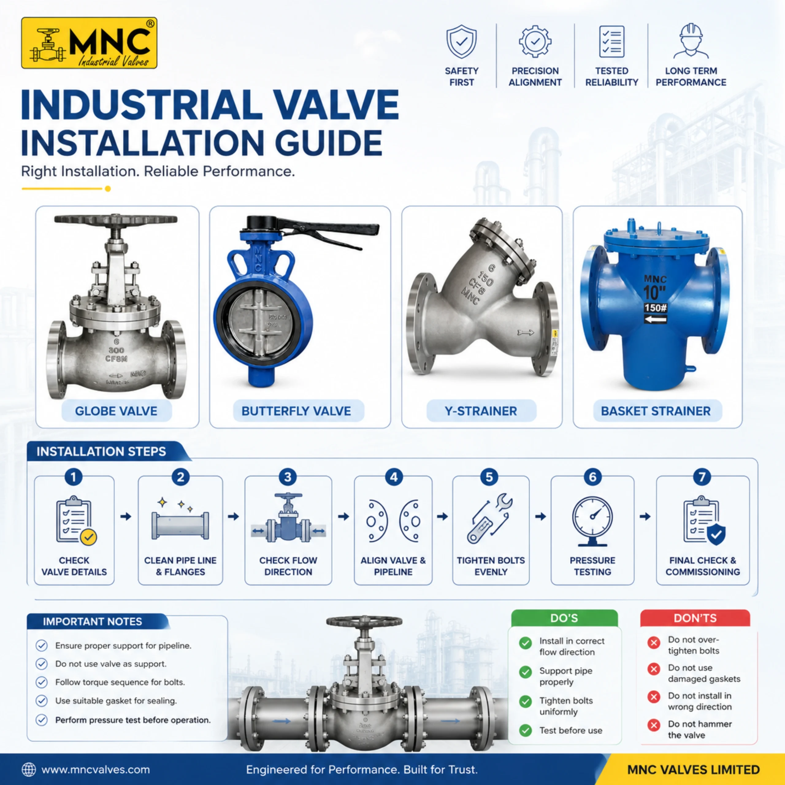
This comprehensive engineering guide explains inspection, storage, handling, lifting, installation, gasket selection, bolt tightening, automation installation, hydro testing, commissioning, troubleshooting, and maintenance best practices for industrial valves.
Industrial valves are critical components used to isolate, regulate, divert, or control the flow of liquids, gases, steam, chemicals, slurry, wastewater, and other process media. Proper installation directly affects reliability, leakage performance, maintenance requirements, operating efficiency, and service life.
This guide has been developed by MNC Valves Limited to support engineers, EPC contractors, consultants, commissioning teams, maintenance personnel, and industrial end users.
Many valve failures originate from improper storage, incorrect handling, poor flange alignment, wrong gasket selection, improper bolt tightening, or incomplete commissioning rather than manufacturing defects.
Valve installation is not simply connecting a valve between two flanges or pipe ends. Proper installation directly affects safety, leakage performance, maintenance requirements, operating efficiency, reliability, and service life.
Proper installation minimizes leakage risks, protects personnel, improves operational safety, and reduces unplanned shutdowns.
Correct installation practices help ensure consistent valve performance throughout the equipment life cycle.
Correct alignment, gasket selection, testing, and commissioning improve sealing performance and process efficiency.
| Improper Installation | Possible Consequence |
|---|---|
| Pipeline Debris | Seat Damage & Leakage |
| Wrong Gasket | Flange Leakage |
| Misalignment | Body Stress & Failure |
| Improper Bolt Tightening | Leakage & Gasket Damage |
| Poor Commissioning | Operational Problems |
| Incorrect Actuator Setup | Automation Failure |
A significant percentage of field valve failures originate from installation, handling, alignment, gasket, bolting, or commissioning issues rather than manufacturing defects.
The following installation sequence represents recommended industry best practice for industrial valve installation and commissioning.
Following a structured installation sequence significantly reduces leakage risk, startup problems, and future maintenance requirements.
Every valve should be inspected before installation to verify suitability, specification compliance, and physical condition.
| Inspection Item | Check Required | Status |
|---|---|---|
| Valve Type | Matches Specification | ✓ |
| Pressure Class | Matches Design Conditions | ✓ |
| Material | Compatible With Media | ✓ |
| Accessories | Installed & Undamaged | ✓ |
| Nameplate | Legible & Correct | ✓ |
| Physical Condition | No Visible Damage | ✓ |
Inspection records should be maintained as part of project quality documentation and commissioning records.
Before installing any industrial valve, a complete inspection should be performed to verify that the valve is suitable for the intended service conditions and remains free from shipping, storage, or handling damage.
A systematic pre-installation inspection significantly improves reliability, reduces commissioning issues, and helps prevent premature valve failure.
| Inspection Item | Verification Required | Importance |
|---|---|---|
| Valve Type | Matches Approved Specification | Critical |
| Valve Size | Matches Piping System | Critical |
| Pressure Class | Suitable For Operating Conditions | Critical |
| Material | Compatible With Process Media | Critical |
| End Connection | Matches Piping Design | Critical |
| Tag Number | Matches Project Documents | High |
| Accessories | Complete & Undamaged | High |
| Nameplate | Legible & Accurate | High |
| Physical Condition | No Visible Damage | Critical |
Verify that the valve nameplate information matches project specifications and purchase requirements.
Carefully inspect the valve for any visible signs of transportation or handling damage.
Protective covers and end caps should remain installed until installation begins.
Inspection findings should be documented and retained as part of project quality records, commissioning documentation, and traceability requirements.
Proper storage, handling, and lifting are essential for preserving valve performance before installation. Damage occurring during storage, transportation, or lifting can significantly reduce reliability and service life.
Many field problems originate from improper handling rather than manufacturing defects. Therefore, valves should be protected from contamination, corrosion, impact, and excessive mechanical loading throughout storage and installation activities.
| Storage Requirement | Recommended Practice | Importance |
|---|---|---|
| End Protection | Keep Covers Installed | Critical |
| Moisture Protection | Dry Storage Area | Critical |
| Contamination Protection | Prevent Dirt Entry | Critical |
| Corrosion Prevention | Periodic Inspection | High |
| Accessory Protection | Protect Actuators & Instruments | High |
Actuators, positioners, solenoid valves, limit switch boxes, tubing, and wiring are not designed to support lifting loads. Using these components as lifting points may result in hidden mechanical damage, calibration problems, or complete automation failure.
| Valve Type | Preferred Lifting Method | Special Attention Required |
|---|---|---|
| Manual Ball Valve | Body Support | Protect End Connections |
| Butterfly Valve | Body Support | Protect Disc & Seat |
| Gate Valve | Lifting Lug / Body Support | Protect Stem |
| Knife Edge Gate Valve | Lifting Lug | Protect Gate & Actuator |
| Actuated Valve | Lifting Lug / Body Support | Protect Accessories |
| Flush Bottom Valve | Lifting Lug | Protect Seat Area |
Keep end protectors installed until installation begins. Protect valves from contamination, corrosion, impact loading, and improper lifting. Proper storage and handling significantly improve reliability and reduce commissioning problems.
The quality of valve installation depends not only on the valve itself but also on the tools, measuring instruments, testing equipment, and safety systems used during installation and commissioning. Proper tools improve installation quality, reduce leakage risk, prevent equipment damage, and support safe plant operation.
| Tool / Equipment | Purpose | Recommended Application |
|---|---|---|
| Torque Wrench | Controlled Bolt Tightening | Flanged Valve Installation |
| Spirit Level | Alignment Verification | Valve & Pipeline Alignment |
| Feeler Gauge | Gap Verification | Flange Parallelism Check |
| Vernier Caliper | Dimensional Verification | Inspection & Measurement |
| Chain Block | Controlled Lifting | Large Valve Handling |
| Hydro Test Pump | Pressure Testing | Testing & Commissioning |
| Pressure Gauge | Pressure Monitoring | Testing & Verification |
| Multimeter | Electrical Verification | Electric Actuators |
For pneumatic actuated valves, proper air supply equipment is essential for reliable operation.
| Instrument | Calibration Required | Importance |
|---|---|---|
| Torque Wrench | Yes | Critical |
| Pressure Gauge | Yes | Critical |
| Vernier Caliper | Yes | High |
| Multimeter | Recommended | High |
| Signal Generator | Recommended | High |
| Activity | Recommended Tools |
|---|---|
| Flange Assembly | Torque Wrench, Spanner Set |
| Alignment Verification | Spirit Level, Feeler Gauge |
| Hydro Testing | Hydro Pump, Pressure Gauge |
| Actuator Installation | Multimeter, Signal Tester |
| Commissioning | Testing Instruments & Gauges |
All installation, testing, lifting, and commissioning activities should be performed using approved tools, calibrated instruments, certified lifting equipment, and appropriate personal protective equipment.
Correct tools improve installation quality, reduce rework, support accurate testing, and significantly improve long-term valve reliability. Never compromise on tool quality, calibration status, or safety equipment during installation activities.
Proper installation is essential for safe, reliable, and leak-free valve operation. The following procedure represents recommended engineering practice for industrial valve installation across most applications. Site-specific requirements, project specifications, and manufacturer recommendations should always be followed.
        1

    8       5

7               3

    6       4

        2
Recommended sequence: 1 → 5 → 2 → 6 → 3 → 7 → 4 → 8
| Installation Stage | Critical Check | Risk If Ignored |
|---|---|---|
| Pipeline Cleaning | Debris Removal | Seat Damage |
| Flow Direction | Arrow Verification | Incorrect Operation |
| Alignment | Parallel Flanges | Body Stress |
| Gasket Installation | Correct Material | Leakage |
| Bolt Tightening | Cross Pattern | Uneven Compression |
| Support Verification | Mechanical Stability | Premature Failure |
| Operational Check | Full Travel | Commissioning Failure |
Successful valve installation is achieved through proper inspection, clean piping, correct alignment, suitable gasket selection, controlled bolt tightening, operational verification, pressure testing, and structured commissioning procedures.
Different valve designs have different installation requirements. Although the basic installation principles remain similar, certain valve types require additional precautions to ensure proper operation, long service life, and reliable performance.
Ball valves are quarter-turn isolation valves widely used in industrial piping systems.
Standard ball valves should generally be used for isolation service unless specifically designed for throttling applications.
Butterfly valves require careful installation to prevent disc interference and seat damage.
Knife Edge Gate Valves are commonly used for slurry, wastewater, pulp & paper, mining, and abrasive services.
The gate must move freely without obstruction. Any restriction may result in improper sealing or premature wear.
Flush Bottom Valves are designed for installation at the bottom outlet of tanks, reactors, and process vessels.
Y Type Flush Bottom Ball Valves combine the advantages of flush bottom design with quarter-turn ball valve operation.
| Valve Type | Critical Installation Check | Main Risk |
|---|---|---|
| Ball Valve | Seat Protection | Seat Damage |
| Butterfly Valve | Disc Clearance | Disc Interference |
| Gate Valve | Stem Orientation | Operating Problems |
| Globe Valve | Flow Direction | Poor Performance |
| Check Valve | Flow Arrow | Reverse Flow Failure |
| Strainer | Screen Accessibility | Maintenance Difficulty |
| Knife Edge Gate Valve | Gate Clearance | Improper Sealing |
| Y Type Flush Bottom Valve | Drainability | Product Retention |
| Y Type Flush Bottom Ball Valve | Full Port Flow | Incomplete Drainage |
Always install valves according to valve type, service conditions, flow requirements, and manufacturer recommendations. A procedure suitable for one valve type may not be suitable for another.
Proper gasket selection is essential for achieving leak-free flange connections. The gasket must be compatible with the process media, pressure, temperature, flange design, and operating conditions.
Incorrect gasket selection remains one of the most common causes of flange leakage in industrial piping systems.
Compressed Asbestos Free Gasket
Polytetrafluoroethylene Gasket
High Temperature Sealing Solution
Ring Type Joint Gasket
| Gasket Type | Pressure Capability | Temperature Capability | Typical Applications |
|---|---|---|---|
| CAF | Low To Medium | Medium | Water, Air, Utilities |
| PTFE | Medium | Medium | Chemical Service |
| Graphite | Medium To High | High | Steam & High Temperature |
| Spiral Wound | High | High | Process Industry |
| RTJ | Very High | High | Critical Service |
| Elastomer | Low | Low To Medium | Water Service |
| Common Mistake | Possible Result |
|---|---|
| Wrong Gasket Material | Chemical Attack Or Leakage |
| Damaged Gasket | Premature Leakage |
| Reusing Gaskets | Sealing Failure |
| Off-Center Installation | Uneven Compression |
| Dirty Flange Faces | Leakage Path Formation |
| Over Tightening | Gasket Damage |
| Under Tightening | Insufficient Seal |
Many flange leakage problems originate from incorrect gasket selection, improper gasket installation, poor flange condition, or uneven bolt tightening rather than defects in the valve itself.
Always select gasket materials according to process conditions, pressure class, temperature requirements, media compatibility, flange design, and project specifications. Never assume one gasket type is suitable for all applications.
Proper flange alignment and controlled bolt tightening are critical for achieving leak-free valve installations. Many leakage problems occur due to poor alignment practices, improper gasket compression, incorrect bolt selection, or uneven tightening methods.
| Inspection Item | Verification Required | Importance |
|---|---|---|
| Flange Face Condition | No Damage | Critical |
| Parallel Alignment | Uniform Gap | Critical |
| Concentric Position | Center Alignment | Critical |
| Fastener Condition | Good Threads | High |
| Gasket Seating Area | Clean Surface | Critical |
| Support Condition | No External Loading | High |
Where specified, approved lubricants may be applied to bolt threads to improve tightening consistency and reduce friction variation.
        1

    8       5

7               3

    6       4

        2
Recommended tightening sequence: 1 → 5 → 2 → 6 → 3 → 7 → 4 → 8
| Common Mistake | Possible Result |
|---|---|
| Using Valve To Pull Pipes Together | Body Stress & Leakage |
| Random Tightening | Uneven Compression |
| Single Pass Tightening | Leakage Risk |
| Over Tightening | Gasket Damage |
| Under Tightening | Insufficient Seal |
| Damaged Fasteners | Joint Failure |
| Ignoring Alignment | Premature Failure |
Never use flange bolts to force misaligned piping into position. The piping system must be aligned before valve installation. Using the valve as a pipe alignment tool may result in leakage, body distortion, excessive operating torque, and reduced service life.
Successful flange joints require clean flange faces, correct gasket selection, proper alignment, suitable fasteners, cross-pattern tightening, controlled torque application, and final verification before pressure testing.
Actuated valves combine industrial valves with automation systems to enable remote operation, process control, safety functions, and integration with PLC, DCS, and SCADA systems.
Proper installation requires correct integration of the valve, actuator, accessories, air supply system, electrical wiring, feedback devices, and control systems.
Double acting actuators use compressed air for both opening and closing operations.
Single acting actuators use compressed air in one direction and spring return in the opposite direction.
Air Filter Regulator Lubricator
| Device | Verification Required | Status Before Commissioning |
|---|---|---|
| Actuator | Travel Verification | Mandatory |
| Solenoid Valve | Functional Test | Mandatory |
| Limit Switch | Feedback Verification | Mandatory |
| Positioner | Calibration Check | Mandatory |
| AFRL | Pressure Verification | Mandatory |
| Manual Override | Operation Verification | Recommended |
Windtex automation solutions are designed for reliable integration with ball valves, butterfly valves, gate valves, knife edge gate valves, flush bottom valves, and other industrial valve applications requiring pneumatic or electric automation.
| Common Installation Error | Possible Result |
|---|---|
| Incorrect Air Pressure | Actuator Failure |
| Incorrect Wiring | No Operation |
| Incorrect Calibration | Position Error |
| Poor Air Quality | Premature Wear |
| Wrong Actuator Size | Insufficient Torque |
| Incorrect Feedback Setup | Control System Error |
Actuated valves should always be installed, tested, calibrated, and commissioned as a complete automation package. Proper integration of the valve, actuator, accessories, air supply system, and control system is essential for long-term reliability.
Pressure testing is one of the most critical stages of valve installation and commissioning. It verifies the integrity of the valve, piping system, flange joints, gaskets, and associated equipment before the system is placed into service.
Proper testing helps identify leakage points, installation errors, damaged components, and assembly issues before plant startup.
| Inspection Area | Verification Required |
|---|---|
| Valve Body | No Leakage |
| Bonnet Joint | No Leakage |
| Flange Connections | No Leakage |
| Threaded Connections | No Leakage |
| Automation Tubing | No Leakage |
| Accessories | Proper Function |
| HYDRO TEST RECORD FORMAT | |
|---|---|
| Project | ________________ |
| Work Order No. | ________________ |
| Valve Tag No. | ________________ |
| Valve Type | ________________ |
| Valve Size | ________________ |
| Pressure Class | ________________ |
| Test Medium | ________________ |
| Test Pressure | ________________ |
| Test Duration | ________________ |
| Result | PASS / FAIL |
| Inspector | ________________ |
| Date | ________________ |
| Common Testing Error | Possible Consequence |
|---|---|
| Rapid Pressurization | System Damage |
| Trapped Air | Inaccurate Results |
| Uncalibrated Gauge | False Readings |
| Incomplete Inspection | Undetected Leakage |
| Poor Documentation | Traceability Issues |
| Ignoring Minor Leakage | Future Failure |
Pneumatic testing stores significantly more energy than hydrostatic testing. Appropriate safety procedures, exclusion zones, and qualified personnel are essential during pneumatic pressure testing activities.
Pressure testing should always be completed before commissioning. Identifying and correcting problems during testing is significantly less expensive than dealing with failures after plant startup.
Commissioning is the final verification stage before a valve system is released for normal operation. Proper commissioning confirms that installation, testing, automation, instrumentation, and operational requirements have been completed successfully.
A structured commissioning process helps identify problems before startup and ensures safe, reliable, and efficient valve operation.
| Commissioning Check | Status |
|---|---|
| Installation Complete | □ |
| Pressure Test Passed | □ |
| No Leakage Observed | □ |
| Valve Operates Correctly | □ |
| Accessories Function Correctly | □ |
| Control Signals Verified | □ |
| Feedback Signals Verified | □ |
| Documentation Complete | □ |
| COMMISSIONING REPORT FORMAT | |
|---|---|
| Project Name | ________________ |
| Work Order No. | ________________ |
| Valve Tag No. | ________________ |
| Valve Type | ________________ |
| Valve Size | ________________ |
| Actuator Type | ________________ |
| Pressure Test Result | PASS / FAIL |
| Functional Test Result | PASS / FAIL |
| Commissioning Result | PASS / FAIL |
| Commissioned By | ________________ |
| Witnessed By | ________________ |
| Date | ________________ |
| Issue | Possible Cause |
|---|---|
| Valve Does Not Open | Supply Or Wiring Issue |
| Valve Does Not Close | Travel Adjustment Issue |
| No Feedback Signal | Limit Switch Problem |
| Slow Operation | Insufficient Air Pressure |
| Incorrect Position | Calibration Error |
| Control System Alarm | Communication Failure |
A valve should never be released for plant operation until installation, testing, automation verification, control verification, and documentation activities have been completed successfully.
Successful commissioning confirms that the valve, actuator, accessories, piping system, and control system function together as a complete operational package ready for service.
Many valve failures are not caused by manufacturing defects but by installation errors, handling mistakes, incorrect commissioning practices, or poor maintenance procedures. Understanding these common mistakes helps improve reliability, safety, and service life.
| No. | Common Mistake | Possible Consequence | Corrective Action |
|---|---|---|---|
| 1 | Using Valve To Pull Pipes Into Alignment | Body Stress, Leakage | Align Piping Before Installation |
| 2 | Ignoring Flow Direction | Incorrect Operation | Verify Flow Arrow |
| 3 | Installing Wrong Gasket | Leakage | Select Correct Gasket |
| 4 | Reusing Old Gaskets | Seal Failure | Use New Gaskets |
| 5 | Over Tightening Bolts | Gasket Damage | Use Controlled Torque |
| 6 | Under Tightening Bolts | Leakage | Follow Tightening Procedure |
| 7 | Skipping Pipeline Cleaning | Seat Damage | Flush Pipeline Before Installation |
| 8 | Improper Valve Storage | Corrosion & Damage | Follow Storage Procedures |
| 9 | Incorrect Valve Orientation | Operational Problems | Follow Installation Drawing |
| 10 | No Support For Heavy Valves | Mechanical Stress | Provide Adequate Support |
| 11 | Ignoring Pressure Testing | Undetected Leakage | Perform Testing |
| 12 | Poor Air Quality | Actuator Failure | Install AFRL System |
| 13 | Incorrect Wiring | Automation Failure | Verify Electrical Connections |
| 14 | Incorrect Calibration | Position Errors | Perform Calibration |
| 15 | Incomplete Commissioning | Startup Problems | Complete Commissioning Checklist |
Using the valve body to force piping into alignment is one of the most damaging installation mistakes and may permanently affect valve performance.
Incorrect gasket selection and improper bolt tightening remain among the most common causes of flange leakage.
Skipping testing and commissioning can result in costly plant shutdowns and emergency maintenance.
Most installation-related failures are preventable. Following structured installation, testing, and commissioning procedures significantly improves valve reliability and reduces lifecycle costs.
Every installation activity should be documented, inspected, tested, and verified before the valve is released into service. Prevention is always less expensive than corrective maintenance.
Troubleshooting should follow a structured approach to identify root causes and implement corrective actions efficiently. Random adjustments often increase downtime and may create additional problems.
| Problem | Possible Cause | Corrective Action |
|---|---|---|
| Valve Hard To Operate | Debris, Corrosion, Seat Damage | Inspect & Clean Valve |
| Excessive Torque | Misalignment, Internal Damage | Inspect Valve Internals |
| Internal Leakage | Seat Damage | Inspect Seating Components |
| External Leakage | Packing Or Gasket Issue | Repair Or Replace |
| Vibration | Flow Instability | Review System Conditions |
| Problem | Possible Cause | Corrective Action |
|---|---|---|
| No Operation | No Air Supply | Check Air System |
| Slow Operation | Low Air Pressure | Adjust Air Pressure |
| Jerky Movement | Contaminated Air | Inspect AFRL Unit |
| Incomplete Travel | Travel Stop Setting | Adjust Travel Stops |
| Air Leakage | Loose Fittings | Tighten Connections |
| Problem | Possible Cause | Corrective Action |
|---|---|---|
| No Operation | No Power Supply | Verify Voltage |
| Wrong Rotation | Incorrect Wiring | Correct Wiring |
| Stops Midway | Limit Setting Issue | Adjust Limits |
| Motor Overheating | Overloading | Check Torque Requirement |
| Alarm Indication | Control System Fault | Review Diagnostics |
| Problem | Possible Cause | Corrective Action |
|---|---|---|
| No Switching | No Power Supply | Check Voltage |
| Coil Heating | Voltage Mismatch | Verify Coil Rating |
| Slow Response | Contamination | Clean Solenoid |
| Air Leakage | Seal Damage | Replace Seal |
| Problem | Possible Cause | Corrective Action |
|---|---|---|
| No Feedback Signal | Incorrect Cam Setting | Adjust Cam |
| Wrong Position Indication | Misalignment | Re-adjust Position |
| Intermittent Signal | Loose Wiring | Inspect Wiring |
| PLC Error | Signal Failure | Verify Connections |
| Problem | Possible Cause | Corrective Action |
|---|---|---|
| Position Error | Calibration Drift | Recalibrate |
| Slow Response | Air Restriction | Inspect Air Supply |
| Hunting | Poor Tuning | Adjust Settings |
| No Movement | Signal Loss | Verify Input Signal |
| Leakage Type | Possible Cause | Corrective Action |
|---|---|---|
| Flange Leakage | Gasket Issue | Inspect Gasket |
| Packing Leakage | Packing Wear | Replace Packing |
| Body Leakage | Mechanical Damage | Repair Or Replace |
| Seat Leakage | Seat Damage | Inspect Internals |
| Tubing Leakage | Loose Fitting | Tighten Connection |
Always identify the root cause before replacing components. Replacing parts without proper diagnosis often increases downtime and maintenance costs.
Maintain detailed troubleshooting records, corrective actions, and test results. Historical maintenance data significantly improves future troubleshooting efficiency and reliability.
A structured checklist helps ensure that critical installation, inspection, testing, and commissioning activities are completed before the valve is released for operation.
| SITE INSTALLATION CHECKLIST | |
|---|---|
| Correct Valve Installed | □ |
| Valve Size Verified | □ |
| Pressure Class Verified | □ |
| Material Verified | □ |
| Flow Direction Verified | □ |
| Pipeline Cleaned | □ |
| Flanges Aligned | □ |
| Correct Gasket Installed | □ |
| Bolts Tightened Properly | □ |
| Valve Supports Installed | □ |
| Accessories Installed | □ |
| QUALITY ASSURANCE CHECKLIST | |
|---|---|
| Valve Inspection Completed | □ |
| Nameplate Verified | □ |
| Material Verification Completed | □ |
| Visual Inspection Completed | □ |
| Installation Verified | □ |
| Pressure Testing Completed | □ |
| Leakage Check Completed | □ |
| Documentation Complete | □ |
| Records Filed | □ |
| COMMISSIONING CHECKLIST | |
|---|---|
| Valve Opens Correctly | □ |
| Valve Closes Correctly | □ |
| Full Travel Verified | □ |
| No Leakage Observed | □ |
| Air Supply Verified | □ |
| Electrical Supply Verified | □ |
| Control Signals Verified | □ |
| Feedback Signals Verified | □ |
| Final Approval Obtained | □ |
| MASTER VALVE INSTALLATION RECORD | ||
|---|---|---|
| Project Name | ______________________ | |
| Work Order No. | ______________________ | |
| Valve Tag No. | ______________________ | |
| Valve Type | ______________________ | |
| Valve Size | ______________________ | |
| Pressure Class | ______________________ | |
| Installation Date | ______________________ | |
| Installed By | ______________________ | |
| Inspected By | ______________________ | |
| Tested By | ______________________ | |
| Commissioned By | ______________________ | |
| Final Status | PASS / FAIL | |
A valve should not be released for operation until installation, inspection, testing, commissioning, documentation, and approval activities have been completed successfully.
Checklists improve consistency, reduce human error, strengthen traceability, and support quality assurance requirements throughout the installation lifecycle.
Different industries present different operating conditions, process requirements, media characteristics, safety expectations, and maintenance challenges. Installation practices should always consider the actual service conditions of the plant.
Common Valves: Ball Valves, Butterfly Valves, Check Valves, Y Strainers.
Common Valves: Knife Edge Gate Valves, Butterfly Valves, Check Valves.
Common Valves: PTFE Lined Ball Valves, PTFE Lined Butterfly Valves, Flush Bottom Valves.
Common Valves: Ball Valves, Gate Valves, Globe Valves, Check Valves.
Common Valves: Gate Valves, Globe Valves, Check Valves.
Common Valves: Ball Valves, Butterfly Valves, Control Valves.
Common Valves: Ball Valves, Butterfly Valves, Check Valves.
Common Valves: Knife Edge Gate Valves, Metal Seated Ball Valves, Heavy Duty Butterfly Valves.
Common Valves: Y Type Flush Bottom Valves, Y Type Flush Bottom Ball Valves.
| Industry | Critical Requirement | Recommended Valve Types |
|---|---|---|
| Water Treatment | Corrosion Resistance | Ball, Butterfly, Check |
| Wastewater | Solids Handling | Knife Edge Gate |
| Chemical | Chemical Compatibility | Lined Valves, Flush Bottom |
| Oil & Gas | Pressure & Safety | Ball, Gate, Globe |
| Power | Temperature Resistance | Gate, Globe, Check |
| HVAC | Flow Control | Ball, Butterfly |
| Marine | Corrosion Protection | Ball, Butterfly |
| Slurry | Abrasion Resistance | Knife Edge Gate |
| Reactor Bottom Discharge | Drainability | Flush Bottom Valves |
A valve installation suitable for one industry may not be suitable for another. Always consider media characteristics, operating conditions, maintenance requirements, and industry-specific standards before installation.
Successful valve installations are achieved by matching the valve design, materials, sealing system, automation package, and installation method to the actual service conditions of the application.
To support engineers, consultants, EPC contractors, maintenance teams, and industrial end users, MNC Valves Limited provides practical engineering templates, checklists, records, and technical resources that can be adapted for project documentation and quality systems.
Printable installation verification checklist for site engineers and commissioning teams.
Download TemplatePressure testing and hydrostatic testing record format for project documentation.
Download TemplateStructured commissioning verification record for installation and startup activities.
Download TemplateValve troubleshooting guide for maintenance engineers and field service teams.
Download TemplatePreventive maintenance and service history recording template.
Download TemplateIncoming inspection, installation inspection, and quality verification record.
Download TemplateReference guide for selecting valve types according to service conditions.
Download GuideActuator, solenoid, positioner, and accessory specification format.
Download Template| Resource | Purpose | Primary Users |
|---|---|---|
| Installation Checklist | Installation Verification | Site Engineers |
| Hydro Test Report | Pressure Test Documentation | QA / QC Teams |
| Commissioning Report | Startup Documentation | Commissioning Teams |
| Troubleshooting Sheet | Maintenance Support | Maintenance Engineers |
| Maintenance Log | Service Records | Plant Maintenance Teams |
| Valve Data Sheet | Technical Records | Engineering Teams |
| Inspection Report | Quality Verification | QA / QC Engineers |
| Automation Data Sheet | Automation Documentation | Instrumentation Teams |
Additional technical resources available from MNC Valves Limited:
All engineering documents should be reviewed and approved according to project specifications, customer requirements, applicable standards, and site procedures before use.
Standardized formats improve traceability, quality control, documentation consistency, and long-term maintenance management throughout the valve lifecycle.
The following frequently asked questions address common installation, operation, testing, commissioning, maintenance, and automation concerns encountered by engineers, contractors, maintenance teams, consultants, and industrial end users.
Proper installation improves reliability, safety, performance, and service life.
No. Pipes must be aligned independently before valve installation.
Yes. All valves should be inspected before installation.
No. Damaged valves should be repaired or replaced before installation.
Yes. Nameplate information must match project requirements.
Store valves in clean, dry, protected conditions.
Yes, until installation begins.
No. Actuators are not designed for lifting loads.
No. Always use approved lifting points.
It prevents corrosion, contamination, and mechanical damage.
Generally, no. New gaskets are recommended.
Common causes include incorrect gaskets, poor alignment, or improper tightening.
A bolt tightening sequence that provides uniform gasket compression.
It ensures proper gasket loading and leak prevention.
Yes, before gasket installation.
To verify system integrity and identify leakage.
Generally, yes.
Yes, calibrated instruments should be used.
It verifies the shut-off capability of a valve.
No. Commissioning is essential before operation.
Possible causes include debris, corrosion, or internal damage.
Seat damage or contamination may be responsible.
Packing, gasket, or body damage may be present.
Misalignment, deposits, or damaged internals.
Flow instability or incorrect operating conditions.
An actuator using air pressure for both opening and closing.
An actuator using air pressure and spring return.
It controls airflow to pneumatic actuators.
A device providing open and closed position feedback.
A device controlling actuator position according to signal input.
Ball valves, butterfly valves, check valves, and strainers.
Knife edge gate valves and butterfly valves.
Lined valves and flush bottom valves.
Ball, gate, globe, and check valves.
Knife edge gate valves and metal seated valves.
Inspection frequency depends on service conditions and maintenance plans.
To improve traceability and reliability.
No. Periodic inspection and maintenance are recommended.
Operation, leakage, fasteners, packing, accessories, and condition.
It reduces unexpected failures and downtime.
The pressure rating assigned to a valve or flange.
To prevent corrosion and material degradation.
The ability to track valve identification, materials, testing, and records.
Standards help ensure safety, quality, and consistency.
The process of verifying readiness for operation.
Yes, through Windtex Automation solutions.
Yes, installation and application support are available.
Support may be available based on project requirements.
Custom engineered solutions may be offered depending on application requirements.
Use the contact information available on the website.
If your question is not covered above, contact the MNC Valves engineering team for application-specific guidance, automation support, troubleshooting assistance, valve selection recommendations, or technical documentation.
The following engineering best practices have been developed from practical industrial experience across water treatment, wastewater, chemical processing, oil & gas, power generation, HVAC, marine, and general industrial applications. These recommendations help improve reliability, safety, maintainability, and valve service life.
| No. | Engineering Best Practice |
|---|---|
| 1 | Always verify valve specifications before installation. |
| 2 | Inspect valves immediately upon receipt. |
| 3 | Store valves in clean, dry, protected conditions. |
| 4 | Keep protective covers installed until installation. |
| 5 | Never use actuators or handwheels as lifting points. |
| 6 | Always clean pipelines before installation. |
| 7 | Verify flow direction before mounting the valve. |
| 8 | Never use the valve body to pull pipes into alignment. |
| 9 | Ensure proper flange alignment before tightening. |
| 10 | Use only suitable gasket materials. |
| 11 | Use new gaskets whenever practical. |
| 12 | Apply cross-pattern bolt tightening. |
| 13 | Use multi-pass tightening procedures. |
| 14 | Use calibrated tools for critical work. |
| 15 | Provide support for heavy valves and actuators. |
| 16 | Verify valve operation before testing. |
| 17 | Perform pressure testing before commissioning. |
| 18 | Record all test results and inspections. |
| 19 | Use clean and dry instrument air for automation systems. |
| 20 | Verify feedback devices before startup. |
| 21 | Verify actuator travel and calibration. |
| 22 | Complete commissioning before plant release. |
| 23 | Maintain complete installation records. |
| 24 | Follow preventive maintenance programs. |
| 25 | Maintain full traceability throughout the valve lifecycle. |
Most valve failures originate from installation, operation, or maintenance issues rather than manufacturing defects.
Safety procedures must always take priority over production schedules and startup deadlines.
If an activity is not documented, verified, and recorded, it should be considered incomplete.
Reliable valve performance is achieved through a combination of proper engineering, controlled manufacturing, structured inspection, comprehensive testing, full traceability, disciplined installation practices, and professional maintenance procedures.
Every valve should be treated as a critical process component rather than simply a piping accessory.
Even the highest quality valve can fail if installed incorrectly. Installation quality, testing discipline, commissioning verification, and maintenance practices directly influence valve reliability and service life.
The most successful industrial facilities focus on prevention rather than correction. Proper planning, installation, testing, documentation, and maintenance consistently produce the lowest lifecycle costs and highest operational reliability.
MNC Valves Limited is an Indian industrial valve manufacturer specializing in engineered flow control solutions for water treatment, wastewater treatment, chemical processing, power generation, HVAC, marine, oil & gas, and general industrial applications.
Our focus is not only on manufacturing valves but also on delivering reliable, traceable, tested, and application-focused solutions that support long-term plant performance.
Established in 2000 with decades of experience in industrial valve engineering and manufacturing.
Modern manufacturing infrastructure with machining, assembly, testing, inspection, and dispatch capabilities.
Supplying industrial valve solutions to customers across multiple industries and international markets.
Windtex Automation, brought to you by MNC Valves Limited, provides complete valve automation solutions including pneumatic actuators, electric actuators, positioners, solenoid valves, limit switch boxes, AFRL units, and complete automated valve assemblies.
| Capability | Description |
|---|---|
| Manufacturing | Industrial Valve Production |
| Engineering | Application Support |
| Automation | Windtex Automation Solutions |
| Testing | Inspection & Testing Facilities |
| Documentation | Traceability & Records |
| Technical Support | Pre & Post Sales Support |
We are committed to manufacturing and supplying reliable, traceable, tested, and high-quality industrial valves that consistently meet customer requirements, applicable standards, and industry best practices.
Whether you need valve selection support, automation assistance, troubleshooting guidance, installation recommendations, or a project-specific solution, our engineering team is ready to assist.
Contact Our Engineering TeamIndustrial valves are manufactured, tested, inspected, and installed according to internationally recognized standards. These standards help ensure safety, interchangeability, quality, performance, reliability, and compliance across industries worldwide.
| API Standard | Description |
|---|---|
| API 598 | Valve Inspection & Testing |
| API 600 | Steel Gate Valves |
| API 602 | Compact Steel Gate, Globe & Check Valves |
| API 607 | Fire Safe Testing |
| API 609 | Butterfly Valves |
| API 6D | Pipeline Valves |
| ASME Standard | Description |
|---|---|
| ASME B16.5 | Pipe Flanges & Flanged Fittings |
| ASME B16.10 | Face To Face Dimensions |
| ASME B16.11 | Forged Fittings |
| ASME B16.25 | Butt Welding Ends |
| ASME B16.34 | Valves – Flanged, Threaded & Welded End |
| ASME B31.3 | Process Piping |
| ISO Standard | Description |
|---|---|
| ISO 5208 | Pressure Testing Of Metallic Valves |
| ISO 5211 | Actuator Mounting Interface |
| ISO 9001 | Quality Management Systems |
| ISO 14001 | Environmental Management Systems |
| ISO 45001 | Occupational Health & Safety |
| EN Standard | Description |
|---|---|
| EN 12266 | Industrial Valve Testing |
| EN 593 | Butterfly Valves |
| EN 1092-1 | Flanges & Flanged Connections |
| EN 558 | Face To Face Dimensions |
| MSS Standard | Description |
|---|---|
| MSS SP-25 | Valve Marking System |
| MSS SP-61 | Pressure Testing Of Valves |
| MSS SP-67 | Butterfly Valves |
| MSS SP-81 | Knife Gate Valves |
| MSS SP-110 | Ball Valves |
| Activity | Reference Standard |
|---|---|
| Valve Design | API / ASME / EN |
| Valve Testing | API 598 / ISO 5208 / EN 12266 |
| Fire Safe Verification | API 607 / ISO 10497 |
| Automation Mounting | ISO 5211 |
| Quality Systems | ISO 9001 |
| Piping Systems | ASME B31.3 |
Project specifications, customer requirements, local regulations, and industry codes may require additional standards beyond those listed above. Always verify project-specific requirements before selection, installation, testing, or commissioning activities.
International standards provide a common engineering language that improves safety, quality, reliability, interchangeability, and technical consistency across industrial valve applications worldwide.
Understanding common valve terminology helps engineers, consultants, EPC contractors, maintenance teams, and plant operators communicate effectively during valve selection, installation, testing, commissioning, operation, and maintenance activities.
| Term | Definition |
|---|---|
| Actuator | Device used to operate a valve automatically. |
| AFRL | Air Filter Regulator Lubricator used in pneumatic systems. |
| Ball Valve | Quarter-turn valve using a rotating ball for flow control. |
| Body | Main pressure-retaining component of a valve. |
| Bonnet | Pressure-retaining cover attached to the valve body. |
| Butterfly Valve | Quarter-turn valve using a rotating disc. |
| Cavitation | Formation and collapse of vapor bubbles within a fluid system. |
| Check Valve | Valve allowing flow in one direction only. |
| Class Rating | Pressure-temperature rating assigned to valves and flanges. |
| Control Valve | Valve designed for flow regulation. |
| Cv Value | Flow coefficient representing valve flow capacity. |
| Disc | Flow controlling element in butterfly and check valves. |
| Double Acting Actuator | Pneumatic actuator using air pressure in both directions. |
| Duplex Strainer | Dual basket strainer allowing continuous operation. |
| End Connection | Method used to connect a valve to piping. |
| Fail Close | Actuator returns valve to closed position on power loss. |
| Fail Open | Actuator returns valve to open position on power loss. |
| Fire Safe Valve | Valve tested to maintain integrity during fire conditions. |
| Flange | Mechanical connection interface used in piping systems. |
| Flow Direction | Specified direction of fluid movement through a valve. |
| Full Bore | Valve with unrestricted internal flow path. |
| Gate Valve | Linear motion valve used primarily for isolation service. |
| Globe Valve | Linear motion valve commonly used for throttling service. |
| Gland Packing | Sealing material around the valve stem. |
| Hydro Test | Pressure test performed using water. |
| Isolation Valve | Valve used to stop flow completely. |
| Knife Edge Gate Valve | Valve designed for slurry and solids handling applications. |
| Leakage Class | Classification of acceptable leakage performance. |
| Limit Switch Box | Feedback device indicating valve position. |
| Lug Type | Butterfly valve body style with threaded lugs. |
| Manual Override | Manual operating mechanism for automated valves. |
| Modulating Service | Valve operation for flow regulation rather than isolation. |
| NAMUR | Standardized interface for pneumatic automation accessories. |
| On/Off Valve | Valve operating fully open or fully closed. |
| Packing | Stem sealing arrangement preventing external leakage. |
| Pilot Valve | Valve controlling operation of another valve or actuator. |
| Pneumatic Actuator | Actuator powered by compressed air. |
| Positioner | Device controlling actuator position according to input signal. |
| Pressure Class | Pressure-temperature rating of valve equipment. |
| Reduced Bore | Valve having smaller internal flow passage than pipe size. |
| Resilient Seat | Soft sealing seat material providing tight shut-off. |
| RTJ | Ring Type Joint sealing arrangement. |
| Seat | Sealing surface that provides shut-off capability. |
| Single Acting Actuator | Actuator using air pressure and spring return. |
| Solenoid Valve | Electrically operated valve controlling air flow. |
| Stem | Component connecting operator to closure element. |
| Strainer | Device used to remove debris from process fluids. |
| Throttle | Regulate or control flow through a valve. |
| Torque | Rotational force required to operate a valve. |
| Traceability | Ability to track valve history and records. |
| Trunnion Ball Valve | Ball valve with mechanically supported ball design. |
| Wafer Type | Compact valve body installed between flanges. |
| Water Hammer | Pressure surge caused by sudden flow changes. |
| Y Strainer | Strainer with Y-shaped body configuration. |
| Y Type Flush Bottom Valve | Valve designed for reactor and vessel bottom discharge. |
Using correct terminology reduces misunderstandings between engineering, procurement, manufacturing, quality, maintenance, and operations teams.
A common technical vocabulary improves project execution, troubleshooting efficiency, training effectiveness, and communication throughout the valve lifecycle.
Industrial valves are long-term assets that require structured management throughout their lifecycle. Proper lifecycle management improves reliability, reduces downtime, supports traceability, lowers maintenance costs, and maximizes return on investment.
The most successful industrial facilities manage valves as critical process equipment rather than simply purchased components.
| Lifecycle Stage | Primary Responsibility |
|---|---|
| Selection | Engineering Team |
| Procurement | Purchase Department |
| Inspection | QA/QC Department |
| Storage | Stores Department |
| Installation | Site Team |
| Testing | QA/QC Team |
| Commissioning | Commissioning Team |
| Operation | Operations Team |
| Maintenance | Maintenance Department |
| Replacement | Engineering & Maintenance |
Structured lifecycle management significantly improves valve reliability and uptime.
Preventive maintenance reduces emergency shutdowns and repair costs.
Proper lifecycle control reduces operational and maintenance risks.
Ignoring early lifecycle stages such as selection, storage, installation, and testing often leads to costly operational failures later in the valve's service life.
The highest-performing industrial facilities manage valves through a complete lifecycle approach that integrates engineering, procurement, inspection, installation, testing, commissioning, operation, maintenance, and traceability into one controlled system.
Whether you need help with valve selection, troubleshooting, automation, replacement planning, commissioning support, or project-specific requirements, our engineering team is available to assist.
Get assistance selecting the most suitable valve type, material, pressure class, end connection, and automation package for your application.
Need help resolving leakage, high operating torque, actuator problems, calibration issues, or commissioning challenges?
Support for EPC contractors, consultants, OEMs, plant engineers, and maintenance teams.
| Support Area | Available Assistance |
|---|---|
| Valve Selection | Application Review & Recommendations |
| Automation | Windtex Automation Solutions |
| Troubleshooting | Problem Diagnosis & Recommendations |
| Installation | Installation Guidance |
| Testing | Testing Recommendations |
| Commissioning | Startup Assistance |
| Replacement | Replacement Valve Selection |
| Documentation | Technical Documentation Support |
From basic valve selection to complex automated valve packages, MNC Valves Limited provides engineering-driven solutions designed for reliability, safety, performance, and long-term service.
We hope this Industrial Valve Installation Guide has provided valuable technical insights. For project-specific assistance, automation support, troubleshooting guidance, or valve selection recommendations, please contact our engineering team.
Our engineering team can assist with valve selection, installation guidance, automation support, troubleshooting, commissioning assistance, and application-specific recommendations for industrial projects.
Get assistance with valve installation, operation, troubleshooting, maintenance, and commissioning.
Request SupportNeed help selecting the right valve solution for your project? Our engineering team can help.
Talk To EngineeringSupport for Windtex automation systems, actuators, accessories, and automated valve packages.
Explore AutomationEngineered for Reliability
From manual valves to fully automated valve packages, MNC Valves Limited provides engineering support, quality manufacturing, testing, traceability, documentation, and after-sales assistance to help customers achieve reliable and efficient plant operation.
Request A ConsultationProper valve installation is a combination of correct product selection, careful handling, structured installation procedures, controlled testing, professional commissioning, and disciplined maintenance. Following the guidance provided in this document can significantly improve reliability, safety, and service life across a wide range of industrial applications.
The information provided in this Valve Installation Guide is intended for general engineering reference only. Actual installation requirements may vary depending on application, operating conditions, project specifications, applicable standards, and site requirements.
Users are responsible for verifying the suitability of all recommendations before implementation. Project specifications, approved drawings, customer requirements, applicable standards, and safety procedures shall always take precedence over the guidance provided in this document.
Installation, testing, commissioning, and maintenance activities should be performed by qualified personnel only.
For application-specific assistance, please contact MNC Valves Limited.